• Welcome to Tacoma3G.com, a free resource for 2016-2023 Toyota Tacoma owners!

    Tacoma3G is a beginner-friendly 3rd Generation Toyota Tacoma Forum (2016-2023 model-years). We are a community of people who are focused on good information and good vibes.

Solved Seat Heater (heated seats) installation using factory fuse and relay

Asmara

3️⃣ Silver
Tacoma3G Supporter
There are several threads on installing seat heaters aka heated seats but the ones I have seen, have you tap into the fuse box. I like to keep my installs looking stock so I decided to pull the wiring diagram and trace the seat heater wiring to see what I could find.

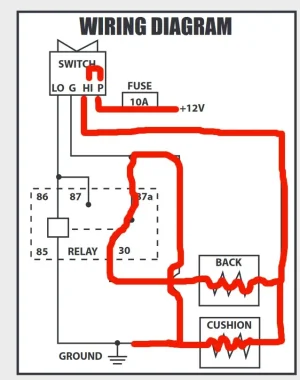
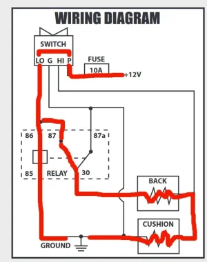
It turned out that in my Tacoma ('21 SR5) it is pre-wired for seat heaters. A little more sleuthing and I found that the factory installed a seat heater fuse but no relay. With the relay installed, the factory wiring worked as expected i.e. the circuit was hot when the truck was running and turned off when the truck was off.

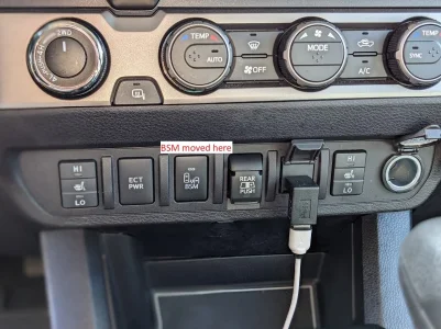
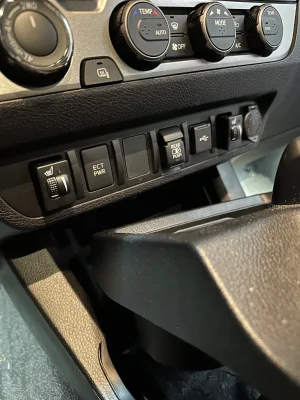
I took some pictures along the way that are attached. The switches look factory except for the fact that the blue light is always on (not controlled by the headlights) and the low/high indicators are orange instead of the green used everywhere else. I've already ordered some green LEDs and plan to change them out to make the switches look even more factory.

What you need to know:
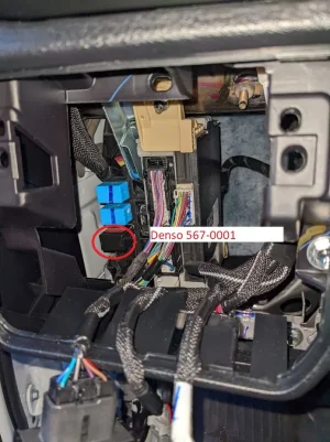
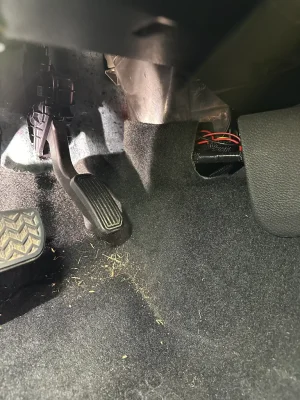
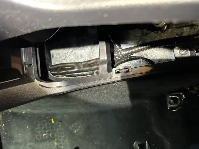
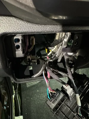
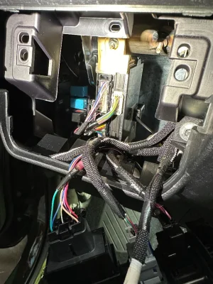
The empty relay location is behind the switches to the left of the steering wheel. You can just reach up behind there and pop out the switch plate to see where the relays go. I bought a genuine 4 pin Denso relay (567-0001) from Amazon but there are tons of cheaper off brands as well. I couldn't find the part number for the factory relay but the 567-0001 supports 20amps which is what the fuse is so I don't anticipate any problems. When I bench tested the seat heaters it pulled about 4 amps a seat on high. Install this relay and the seat heater circuit will be live.

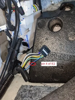
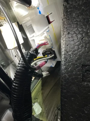
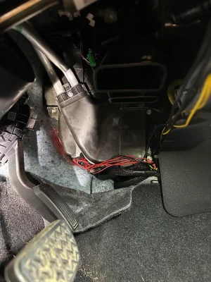
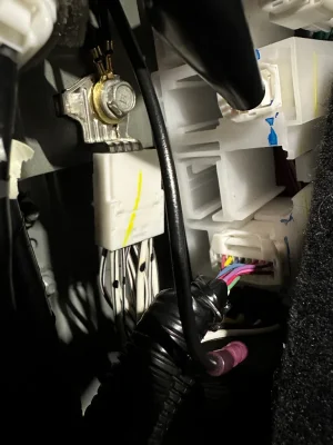
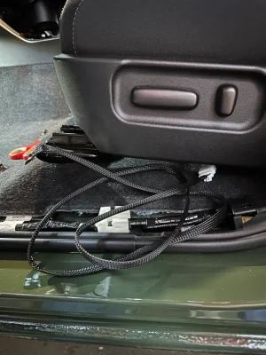
Next I located IE2 which is the junction for the seat heater going to the driver's seat. It is behind the driver's side kick panel. Per the factory diagram, the seat heater is on pin 5 of IE2. During testing, I determined it is actually on pin 4 of IE2. I cut the wire coming out of pin 4 and spliced in my seater heater wiring. I only needed one connection for both seats because I combined the two wiring harnesses behind the switches.

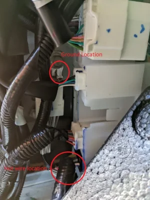
I knew I would need a ground point and, fortunately, there is one right next to IE2.

I wired everything together and the seat heaters work great.

I'd note that you could use this circuit to power any high current device you want (lighting for example) and just re-label the fuse panel. Also, when enabled you have +12v going to both seats so there might be something else you could do with that that might be useful.

I hope this helps some people. I know it will save some time on wiring up a seat heater install.

edit: added term heated seats to help with searching.
 

Attachments

  • hot installed.webp
    hot installed.webp
    173.9 KB · Views: 2,764
  • original locations.webp
    original locations.webp
    76.6 KB · Views: 2,812
  • Relay installed.webp
    Relay installed.webp
    104.2 KB · Views: 3,258
  • switches.webp
    switches.webp
    184.3 KB · Views: 3,228
  • Wire to cut.webp
    Wire to cut.webp
    182.5 KB · Views: 3,073
Last edited:
Not really sure. If you don't have heated seats in your O/R, then unless the O/R commonly comes with heated seats, you will likely have to do some wiring. Some of the wiring will be there like in my SR5 which has some partial wiring. Some may not be. If you are pulling from the junk yard, I'd pull as much of the harness (especially the connectors) that you can.
 
Upvote 0
Would someone be willing to post the wiring diagram for the Clazzio seat heaters? The picture on post #47 is extremely helpful, but I'd really like to understand how everything is connected and how the relays are being used. (Also, how many wire terminals are on the back of the switch.) Thanks!
I've never seen it posted on a forum, and they don't have it on their website (I've looked to try and help people with the install). If you buy a kit, please diagram it out and post it here. I'd also note that I've seen posts saying that they have changed the harness over the years.

If you have a kit and you are trying to understand how it is wired better, I suspect from the harness photos that Clazzio is just using the same system as all the cheap Chinese aftermarket seat heaters. The relays are wired 'backwards' from how you would expect. Normally, a relay is used to allow a switch to turn on and off a high-current device without the current having to go through the switch (which would typically fail due to the high current overheating the switch). The cheap Chinese kits use the relay to change whether the top heating element and the bottom heating element are in series (low switch setting, high resistance, lower current passing through) or parallel (high switch setting, low resistance, more current passing through). It's been a while so I can't recall if they do this by switching the ground wires or the positive wires.
 
Upvote 0
Asmara - thank you for the original post! It's been so helpful! Unfortunately, I don't have the light blue wire coming off the front or back of IE2. I'm going to have to figure out another way to wire-up seat heaters.

I've seen a post by Gutentight on TW showing how the cheap Chinese kits work (schematics below). These kits have one relay, a positive and negative wire, and a switch with four terminals. It looks like the switch light is always on, regardless of whether or not the headlights are turned on. I've wondered if I could buy a second relay and somehow make the cheap kit perform similar to the Clazzio seat heaters, which have two relays, four wires, and only turns on the switch light when the headlights are turned on. Can this even be done with a switch that has only four terminals?

Hopefully someone will post the Clazzio wiring diagram if they stumble on your post before installing them. (That may be me if I bite the bullet and buy the Clazzio kit.) Thanks again!
 

Attachments

  • cheap kit high.webp
    cheap kit high.webp
    26.4 KB · Views: 11
  • cheap kit low.webp
    cheap kit low.webp
    25.4 KB · Views: 10
Upvote 0
Thank you @Asmara for your guide. I also had success with this method in my 2021 SR5 DCSB (trail edition).

I used this kit from Rostra: https://www.rostra.com/toyota-seat-heater-with-custom-control-switch.php which is the same kit as this one https://www.rostra.com/comfortheat-automotive-seat-heater-by-rostra.php, except for the Toyota style switch.

This is my very first time doing any wiring in a car, so forgive me for any improper terminology. I'm trying to write this out as plainly as I can to hopefully help newbies like me!

Similar to other wiring harnesses above, this harness has 4 wires:
1. RED WIRE - Accessory +12v (includes an inline 7.5a fuse)
2. RED/YELLOW STRIPE WIRE - Ignition +12v
3. YELLOW WIRE - Illumination
4. BLACK WIRE - Ground

I used stepdown butt splice connectors to wire the reds together.
https://www.amazon.com/Ancor-Products-Step-Down-Multi-Wire-Connectors/dp/B003O421WE?tag=tacoma3g-20 (probably overkill!). A few generic pink butt connectors as well.

I then bought some generic 16ga stranded wire from Lowe's for the pigtails. I also needed some thinner wire for the pigtail for the illumination splice and had some lying around.

I used this relay from amazon: https://www.amazon.com/Denso-5670001-Relay/dp/B002Y31T0G?tag=tacoma3g-20

Wiring:
1. Wired the driver side reds (#1 and #2) together (therefore going from 2 wires down to 1 pigtail via a butt connector)
2. Wired the passenger side reds (#1 and #2) together (therefore going from 2 wires down to 1 pigtail via a butt connector)
3. Wired the resulting driver and passenger pigtails together (therefore ultimately going from 2 reds on each driver and passenger harness down to a single 16ga wire)
4. Wired the two yellow illumination wires together via a generic pink butt connector.

Connections:
I made the power connection at IE2, so that I only had to make one cut.
1. I cut the blue wire at IE2, added a butt connector, and attached a 3ish ft length of the 16ga wire to run it over under the radio.
2. I connected this wire to the reds (see: wiring step 3)
3. I connected the grounds to the grounding point next to IE2
4. I popped out the left hand drivers side switch panel (pry it out with a trim pry tool) and cut the green illumination wire that leads to the cargo light switch. I added a butt connector on the switch side, connected the switch side to a pigtail, pigtail joined with power side green to another butt connector, and joined the two illumination wires to that. For these connections I used the standard pink butt connectors, just stuck two wires in them because the wires are so small.
5. I ran all the wiring under the driver side footwell and over under the radio and shoved everything as neatly as possible under there. I might try to tidy this up tonight, but space is tight.

I put the switches in the slots, ran the power connectors under the shifter and under the carpet and out the existing hole in the carpet under the seats and made the connection to the heating element. I pulled all the excess connector wire through under the seat, just to bundle it up under there.

I fired it all up, and.....nothing.

Then I realized that I had pulled out the 7.5a inline fuses because I read above that they weren't necessary. I put them back in, and boom. Toasty buns. The inline fuses are absolutely necessary for this kit.

So far I've only installed the driver side heating elements in the seat. Tonight I pull the passenger side. However I tested the passenger side and confirmed I'm getting heat when both of them are turned on.

Thank you all!!!

Pictures attached.
 

Attachments

  • IMG_1595.webp
    IMG_1595.webp
    144.3 KB · Views: 6
  • IMG_1598.webp
    IMG_1598.webp
    233.8 KB · Views: 6
  • IMG_1597.webp
    IMG_1597.webp
    182.4 KB · Views: 6
  • IMG_1596.webp
    IMG_1596.webp
    78 KB · Views: 6
  • IMG_1599.webp
    IMG_1599.webp
    158.6 KB · Views: 6
  • IMG_1602.webp
    IMG_1602.webp
    140.1 KB · Views: 7
  • IMG_1603.webp
    IMG_1603.webp
    186 KB · Views: 7
  • IMG_1604.webp
    IMG_1604.webp
    150.6 KB · Views: 7
  • IMG_1605.webp
    IMG_1605.webp
    173 KB · Views: 7
Last edited:
Upvote 0
Nice work.

One bit of explanation. You do not need the fuses for this install because you are using the Toyota seat heater fuse as part of the factory harness tie in. The intent is to cut out the fuse holders (with fuse) from the aftermarket harness and throw them away.

The reason you don't want the in-line fuses is for troubleshooting and the fact that with this install, they are usually located someplace hard to get to (and will you remember in 5 years?). It doesn't hurt anything, but rather just adds an unnecessary failure point.
 
Upvote 0
Back
Top