• Welcome to Tacoma3G.com, a free resource for 2016-2023 Toyota Tacoma owners!

    Tacoma3G is a beginner-friendly 3rd Generation Toyota Tacoma (2016-2023 model-years) forum. We are a community of people who are focused on good information and good vibes.

Solved Seat Heater (heated seats) installation using factory fuse and relay

Asmara

3️⃣ Silver
Tacoma3G Supporter
There are several threads on installing seat heaters aka heated seats but the ones I have seen, have you tap into the fuse box. I like to keep my installs looking stock so I decided to pull the wiring diagram and trace the seat heater wiring to see what I could find.

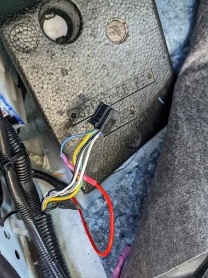
It turned out that in my Tacoma ('21 SR5) it is pre-wired for seat heaters. A little more sleuthing and I found that the factory installed a seat heater fuse but no relay. With the relay installed, the factory wiring worked as expected i.e. the circuit was hot when the truck was running and turned off when the truck was off.

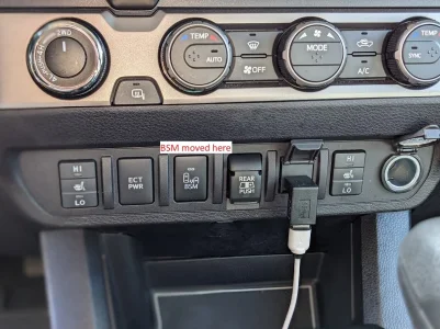
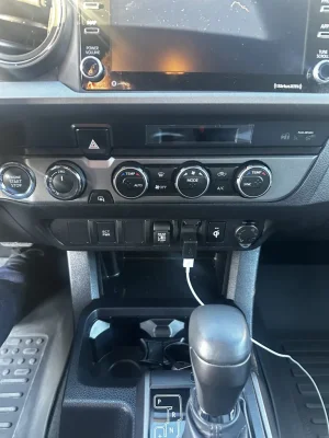
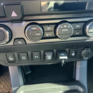
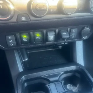
I took some pictures along the way that are attached. The switches look factory except for the fact that the blue light is always on (not controlled by the headlights) and the low/high indicators are orange instead of the green used everywhere else. I've already ordered some green LEDs and plan to change them out to make the switches look even more factory.

What you need to know:
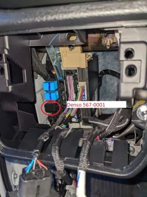
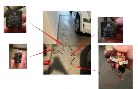
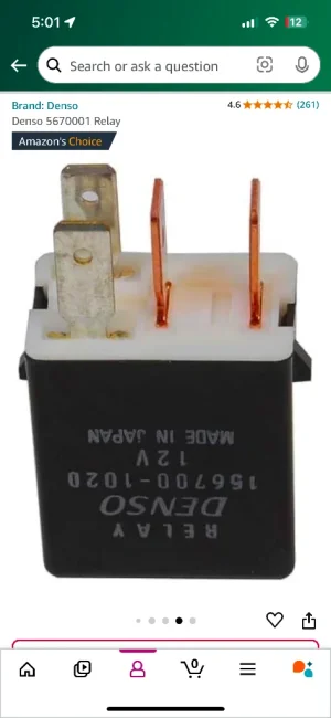
The empty relay location is behind the switches to the left of the steering wheel. You can just reach up behind there and pop out the switch plate to see where the relays go. I bought a genuine 4 pin Denso relay (567-0001) from Amazon but there are tons of cheaper off brands as well. I couldn't find the part number for the factory relay but the 567-0001 supports 20amps which is what the fuse is so I don't anticipate any problems. When I bench tested the seat heaters it pulled about 4 amps a seat on high. Install this relay and the seat heater circuit will be live.

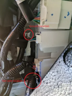
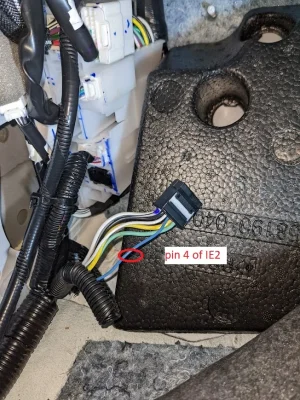
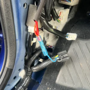
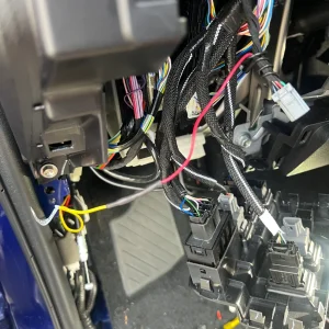
Next I located IE2 which is the junction for the seat heater going to the driver's seat. It is behind the driver's side kick panel. Per the factory diagram, the seat heater is on pin 5 of IE2. During testing, I determined it is actually on pin 4 of IE2. I cut the wire coming out of pin 4 and spliced in my seater heater wiring. I only needed one connection for both seats because I combined the two wiring harnesses behind the switches.

I knew I would need a ground point and, fortunately, there is one right next to IE2.

I wired everything together and the seat heaters work great.

I'd note that you could use this circuit to power any high current device you want (lighting for example) and just re-label the fuse panel. Also, when enabled you have +12v going to both seats so there might be something else you could do with that that might be useful.

I hope this helps some people. I know it will save some time on wiring up a seat heater install.

edit: added term heated seats to help with searching.
 

Attachments

  • hot installed.webp
    hot installed.webp
    173.9 KB · Views: 2,376
  • original locations.webp
    original locations.webp
    76.6 KB · Views: 2,404
  • Relay installed.webp
    Relay installed.webp
    104.2 KB · Views: 2,814
  • switches.webp
    switches.webp
    184.3 KB · Views: 2,777
  • Wire to cut.webp
    Wire to cut.webp
    182.5 KB · Views: 2,647
Last edited:
Can't really tell anything from the photo but you would have a total of 3 relays. The two that are part of your Clazzio kit and one that is the OEM relay. @Athena32 posted above about a Clazzio install using this technique and may answer a PM.
 
Upvote 0
Awesome guide! I'm attempting to wire the Clazzio heated seats to my 21 TRD sport 4x4 currently and I have some questions:
A. Seems like the wire you tapped for power is actually used for the power seats in mine. I can't see that it will matter if I still tap into it (as long as a keep the power for the power seats). Does it? I prefer not to do it this way but I may have to.
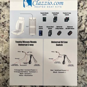
B. My Clazzio kit has 4 wires total to hook up; (1) "Thick Red 12g - Constant (+)", (2) "Thin Red 16g - Switched (+)", (3) "Black Ground (-)", (4) "Yellow - Illumination". I think wire #2 goes to the switch to turn the seat heaters on and off? From the other comments in this tread, it seems like I can wire it to the same place I wire #1?
C. I plan on wiring this to something that only comes on when the car is on (not always on and not acc). Is this ok? Would it be ok to hook up wire 1, 2, and 4 to the same power source?
D. Since I don't really want to tap into the power seats, could I use a fuse tap and add a fuse to something like sunroof? (which mine doesn't have)
E. Does it matter that all the power wires I have found are 16g (including the fuse tap) but the power wire to the seat heaters are 12g?

Edit: I found some charts, it does seem like 12g would be correct here. Seems like there will be a max of ~10amps being pulled and probably over 6 feet in wiring. So the question is, where do I get a 12g wire from? Seems like all the wires in the truck are 16g. Should I run wire #1 directly to the battery and wire #2 to something that turns on when the car is on?
 
Last edited:
Upvote 0
A. Double check the wiring. I have a 2021 SR5 double cab. It it possible that the access cab (if that is what you have) is different. I might have that wiring diagram somewhere but I only saved the double cab diagrams when I accessed the TIS.
B. Yes, you can draw from the same source without a problem. It sounds like your harness uses a relay to switch the seats on and off. Mine ran all the power through the switch but there is nothing wrong with using the same power supply location.
c. Yes. This is ok but I would note that was the whole point of using the empty relay slot. That uses the factory seat heater fuse with the factory relay location. That relay is only energized when the ignition is on.
d. You can use any appropriate circuit. Power is power. The point of this was to keep everything wired as stock as possible (see c).
e. I tested everything on a bench and my seat heaters only pulled 4 amps on high for each seat or 8 amps total. Rule of thumb is 16 gauge can handle 10amp loads. Additionally, and I can't remember exactly where I saw/read this, you'll note that the Toyota seat heater wiring is only 16 gauge. They have it on a 20amp fuse. There was something somewhere about this in the Toyota documentation noting it was OK because the wire was different. If I recall correctly, the insulation was different when I stripped it.
 
Upvote 0
Great post. I have a 2020 sr5 double cab. I have the S/HTR fuse and it appears my relay slot is wired. I have the sky blue wire on the front of IE2 but NOT the back.

I'm thinking it is challenging to add a wire to the fuse box to IE2? Any suggestions for other switched sources for pulling power?
 
Upvote 0
That is the wire. That connector (with the sky blue wire) plugs into IE2. You would be hard-pressed to even see the back of IE2 although someone with an SR didn't have the wire in the front, it did exist in the back.
 
Upvote 0
For an update:

I ended up using the add a fuse ($10 for a pack of 10 from Amazon) to get power directly from my fuse box so I wouldn't have to cut any wires. I used the sun roof for power (always on), the cigarette lighter for on/off (worked with turning the car all the way on), and the first fuse for in the box "panel"? for lighting (worked with headlights). Of note, the lighting on my button doesn't dim with the others, I think the best solution would be to get a "plug and play" wire harness for ~$20 (or cut a wire from a different lighting source). Of course the fuse box cover no longer fits so I'll have to get a Meso customs one if I want to make it clean.

I love the heated seats so far. It works well. It's not nearly as fast as my wife's stock one on her Highlander, it takes it about 3-5 minutes for me to feel the heat when it's all the way up and roughly 10 minutes for me to have to turn it down. I have to turn my wife's down within the first minute of me turning it on. I have my heating pads sandwiched between the cloth seats and Clazzio leather/vinyl seat covers (as recommended by Clazzio). But nonetheless, it's awesome! Thanks again for your help and your great guide.
 
Upvote 0
Thanks for posting these details, OP.

I’ve confirmed I have the heated seats fuse in place in my 21 TRD OR, the empty relay block does have the female terminals installed in it and I am able to find the center console end of IE2, so I’m ordering parts and planning this out.

(I have aftermarket seat heaters already installed, but they tapped into the USB/USB-C charge ports in the arm rest cubby and I want to move them to a different power supply and different switch location).

I am, however, struggling to understand a few key things:

I have Prius switches, which are visually just like yours, a drivers and passengers switch with both low and high, but am not sure how you wired both of them into the center console end of IE2 so they work independently of each other and how the high and low wiring feeds through IE2.

One wiring diagram you posted shows driver side switch wired through IE2 and passenger side wires through IL3, but it appears you combine both seats power wiring and ran them both through IE2? So how do you split the power for the drivers and passenger switched or are you not running them independently of each other?
 
Upvote 0
Sounds like you are overthinking it.

If you already have seat heaters installed, just move the power wires from the USB to IE2 and drop in a relay. The IE2 tap just provides power from the factory location. All the different seat heaters have different wiring but basically you follow those directions and where they tell you to connect to the fuse block or battery, you use IE2.

Ok, I think I understand where we’re straying.

I was thinking you were using the factory wiring, that runs to the center console, to wire in the switches (which would then work through the relay to trigger the power wire to the seats)…but you’re using the aftermarket heated seats wiring for the switches, just replacing the switch itself with the Toyota switch.

The IE2 tap and relay is only to provide switched (ie ignition on) power to the rest of the otherwise aftermarket wiring…

Yep, I was going down a deeper rabbit hole of full stock wiring integration outside of the heating element itself, whoops!

Thanks again and cheers!
 
Upvote 0
Ok, I think I understand where we’re straying.

I was thinking you were using the factory wiring, that runs to the center console, to wire in the switches (which would then work through the relay to trigger the power wire to the seats)…but you’re using the aftermarket heated seats wiring for the switches, just replacing the switch itself with the Toyota switch.

The IE2 tap and relay is only to provide switched (ie ignition on) power to the rest of the otherwise aftermarket wiring…

Yep, I was going down a deeper rabbit hole of full stock wiring integration outside of the heating element itself, whoops!

Thanks again and cheers!
Almost. Mine does not have wiring to the center console.

Different aftermarket systems work differently but on mine the electrical goes IE2 through the switch to the aftermarket relay to the seat heaters. My relay doesn't work like one would expect (separate a high current drawn from passing through a switch). My relay determines if the top heating element and the bottom heating element are in series (low switch setting, high resistence) or parallel (high switch setting, low resistence).

Other systems may want a high current line to go to a relay that is controllerld by the switch. You could use IE2 to both feed a relay in this type of setup as well as to power the switch.
 
Upvote 0
Yep, that’s cleared up for me now. Not sure why I missed the obvious.

I’ll have to figure out how my setup works and adapt it to the Prius switches, but that I can do with my Fluke and a bit of time and some spare wire to extend it all to the center console.

Thanks!
 
Upvote 0
Upvote 0
Sorry to revive this thread but I’m trying to do the same thing using the factory stuff as much as possible for my 23 TRDOR with the Clazzio kit and have some questions.
I have done the following:
1. Checked for SH fuse, it’s there.
2. Checked for continuity between fuse and relay location, which was good.
3. Checked for continuity between relay location and IE2 #4, which was good.
4. Checked for continuity between relay location and IL3 # 7, which was good.
5. A lot of reading on forums 😂
6. A lot of looking on the Toyota TIS program.

I think I have a pretty good grasp about what to do but there’s some blank spots involved.

If I’m reading correctly, I can connect the 4 bare end wires after the switches so I only have to make 4 connections instead of 8.

First I insert the relay into the correct location to make the circuit hot.

Thick red with fuse connects to IE2 #4 or IL3 #7 for power, but cut the fuse off because I don’t want redundant fuses and since there’s already one pre-installed I don’t need it

Black goes to a ground somewhere

The On Wire and the Night Light wire is where I’m confused. Where are you guys connecting these wires? From looking at diagrams and where I’m going to mount the switches (lower left panel) I think for the night light wire I can just tap into the illumination wire on either the ECT Power switch or the mobile charger switch and possibly also tap into the accessory wires for the same switches?
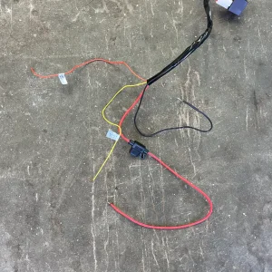
I have attached a picture of the wiring that comes with the kit. There are two sets of these wires, one for each seat.
 

Attachments

  • 17.04.2024_07.52.46_REC.webp
    17.04.2024_07.52.46_REC.webp
    78.9 KB · Views: 166
  • IMG_0847.webp
    IMG_0847.webp
    93.1 KB · Views: 141
Upvote 0
Thick red with fuse connects to IE2 #4 or IL3 #7 for power, but cut the fuse off because I don’t want redundant fuses and since there’s already one pre-installed I don’t need it

Black goes to a ground somewhere

The On Wire and the Night Light wire is where I’m confused. Where are you guys connecting these wires? From looking at diagrams and where I’m going to mount the switches (lower left panel) I think for the night light wire I can just tap into the illumination wire on either the ECT Power switch or the mobile charger switch and possibly also tap into the accessory wires for the same switches?
I have attached a picture of the wiring that comes with the kit. There are two sets of these wires, one for each seat.
Somebody needs to post the wiring diagram (or at least the entire instructions) from the Clazzio kit since that seems to be the most common for questions.

Let's work backward on your questions. Note that I don't have this kit, but based on previous questions, I will make some educated guesses.

If you want the light in the switch to switch on with headlights, the night light wire needs to be connected to a wire that goes +12 when you turn on your headlights. Any wire in the illumination circuit will do.
The 'on' wire goes to the switch and back out to activate the relay. You can actually connect the 'on' wire and the thick red wire together and then to IE2 #4/IL3 #7 for power. The referenced pins in IE2 and IL3 both get their power from the exact same point on the factory relay.
Yep, Black goes to ground. There is a ground point next to IE2 and likely one next to IL3.
 
Upvote 0
OP,

I'm working on installing a pretty basic kit (https://www.ebay.com/itm/364077164564) from ebay. Would there be any issue leaving each seats wiring as is with the exception of wiring the hot (after removing the inline fuses on each) wires together and the ground wires together from each seat and splicing into the IE2 pin you mention the ground you pictured? Essentially, each switch would keep its own relay but would tap power from the same source. My confusion lies in your explanation of the combined wiring behind your switches. I'm having a hard time wrapping my head around it.

Sorry to dig up an old thread. I've searched for hours tonight on TacomaWorld, Tacoma3G, Youtube, etc. trying to find a solution to not using an tap-a-fuse on my truck and you seem to be the only guy who has cracked the code! Lol.
There is no difference.

For the combined wiring, I was just saying instead of doing what you are talking about I basically just extended the IE2 wire to the area behind the switches and made my connections to both seats there. Either location is fine.
 
Upvote 0
has anyone purchased a kit other than the clazzio and installed. looking at the pictures it seems the aftermarket ones and clazzios look identical but clazzios are double the price.
 
Upvote 0
Maybe a dumb question but if I were to eliminate the wireless charger button (things useless and I wouldn’t use it even if it actually functioned) could I use the wire it from the qi plug to give me my 12v and negative for the seats relays?
 
Upvote 0
Maybe a dumb question but if I were to eliminate the wireless charger button (things useless and I wouldn’t use it even if it actually functioned) could I use the wire it from the qi plug to give me my 12v and negative for the seats relays?
I would say unlikely. You'd have to figure out how much current that circuit can support and I doubt it will support seat heaters.
 
Upvote 0
Yea was basically asking because looking at the harness I got the power and ground wires didn’t seem to be long enough to reach over to the fuse panel. But the more I looked at it the power and ground wires to me seem to be very thin and I am just going to return this kit and pay the extra for the clazzio kit.
 
Upvote 0
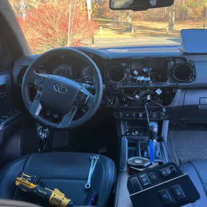
Thanks to this forum an OP I have almost oem heated seats at a fraction of the cost. I purchased clazzio heated seat kit and was able to add the relay and grab power from the blue wire on driver side. I purchased a wire extension for my ect button to relocate to the left of the steering wheel which came with an extra dash illumination lead which I Connected the yellow wire from the clazzio wire harness to. On the passenger side I was able to grab power from the dark blue wire as previously mention in this forum. I grabbed illumination from a wire that I found was off until headlights were turned on. Some pics of during install. Oh and I removed the qi charger button since it’s useless to make room for the passenger side button.
 

Attachments

  • IMG_6176.webp
    IMG_6176.webp
    130.1 KB · Views: 34
  • IMG_6177.webp
    IMG_6177.webp
    213 KB · Views: 34
  • IMG_6178.webp
    IMG_6178.webp
    147.2 KB · Views: 34
  • IMG_6182.webp
    IMG_6182.webp
    393.6 KB · Views: 34
  • IMG_6186.webp
    IMG_6186.webp
    177.6 KB · Views: 31
  • IMG_6188.webp
    IMG_6188.webp
    25.8 KB · Views: 29
  • IMG_6190.webp
    IMG_6190.webp
    128.1 KB · Views: 31
  • IMG_6191.webp
    IMG_6191.webp
    160.2 KB · Views: 32
  • IMG_6204.webp
    IMG_6204.webp
    82.3 KB · Views: 43
Upvote 0
It looks like when the sky blue wire is cut on IE2 it is not re-connected on the back end? it is only spliced into the red wire. Where does this wire originally go and does it need to be connected to the end you cut off?
 
Upvote 0
It looks like when the sky blue wire is cut on IE2 it is not re-connected on the back end? it is only spliced into the red wire. Where does this wire originally go and does it need to be connected to the end you cut off?
The Sky Blue wire at IE2 (if you have it) goes to the driver's side heating element in a factory install. You could technically try to splice into it and use it instead of the wire that comes with your seat heaters, but depending on how the aftermarket ones are set up, it is probably more pain than it is worth. You'd also probably want to find IL3 for the passenger seat (again, assuming you have the wiring) hot.

The wiring goes factory seat heater relay -> 4. At 4 (wherever that is), it splits the output to IE2 and IL3.
 

Attachments

Upvote 0
I just installed the Clazzio heated seat kit under my Clazzio seat covers. Used this thread for ideas on the wiring.

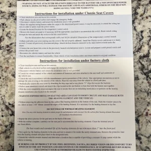
I found my Tacoma has the seated heat fuse, but no wiring to the relay location noted by the OP. So it was on to installing as the Clazzio instructions noted.

I ran a heavier gauge wire into the engine bay and hooked it directly to the batter from the relay. Relay on the Clazzio harness was tucked away in the driver footwear area. The ground was run to the grounding lug near the IE2 connection area. The accessory (switched) power wire from the relay was connected to a switched power fuse in the fuse panel by means of a fuse tap. The illumination wire was run behind my Pioneer headunit and spliced into the idatalink to headunit adapter harnesses orange wire (illumination).

All seems to work well and no factory wires were cut or spliced in to.

Heat from the system seems to be very good and will hopefully make the wife happy as she has missed heated seats since our last vehicle.

Thanks to all the posts here, they helped quite a bit. The only thing I may tackle in the future is changing out the LED in the switch, I used the single switch option from Clazzio, as I have nearly all switch locations filled from the factory.
 
Upvote 0
Back
Top