Well, winter months in the PNW being what they are, and not having a garage in which to work, little has gotten actually done on the truck.
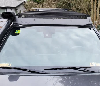
We had some nice weather yesterday, and I've been sick of juggling the new Prinsu roof rack around the living room, so I decided to install it and get my front-facing camera installed.
Figuring that I could just use my Dremel cut-off wheel from the power inverter in the bed, I hauled it out and got to measuring and marking the drip channel molding. Got everything marked and ready to go and.... the power inverter wasn't working. Engine on, nothing. Checked the user manual, and apparently, I have to actually push the button.... but I couldn't find the button. (More on that later.)
So, hooked up to the house, made my cuts through the steel down the middle of the molding, and then drilled out the 1/2" holes through it.
Then saw that what I had initially read as 1/2" was really 3/4". Crud. Do you know how hard it is to try and widen a hole in a chuck of rubber with a spade bit? Got 'em fairly well wallowed out after some doing and cut/drilled the passenger side.
Siliconed the bolt holes, put the spacers in place, and ran the bolts down to hold them on while I reinstalled the molding. Driver side could use some fit adjustment, but I'll take care of that later.
Started installing the sides of the rack, beginning with the passenger side and ran into a little trouble. The cut-out on the side does not *quite* accommodate the TRD desert air intake, even through it's supposed to. Also, one of the lower bits of the rack is actually touching paint when fully installed.
So, contacted Prinsu and waiting to hear back. Meanwhile, I was out of light, so I'd get the camera the next day.
Flash forward, and here I am easily installing the camera bracket, threading the wire along the power line for the winch, and into the engine bay where there's a cable for it waiting to connect it to the Anytime Backup Camera system.
Plugged it in to the waiting RCA plug and..... nada. Well. That's not how it's supposed to work.
So, opened up the switch panel (the PO installed the ABC switch in the left panel where they had removed the switch for (you guessed it) the power inverter.
Pulled out as much wiring as I could reach and groaned. Apparently the PO is not exactly an electrical engineer. All of the connections were where he had twisted (or in a couple of places, tied) the wire ends together and wrapped them in electrical tape. The ground connections were wire tips twisted up and stuck under a nut. It made me sad.
Soooooooo, out cam the stripper, crimper, and spade connectors. replaced the tied together wires and blacktape with spade connectors, dielectric grease, and insulator sleeves.
Replaced the mess of twisted together green wire and red wire tips, with neatly trimmed wires and a wire-nut, replaced the stuck-under-a-nut ground wires with a ring connector that tied them all together, and plugged tried again.
Nada.
So, ensured that everything was plugged in where it should be, removed the front cam's RCA cable from the mix and now the backup cam won't even work.
Did I mention that it was about 38F yesterday? Cold and irritated, I reviewed the installation instructions for the ABC system, and everything was where it should be. clipped the zip tie that was hanging the relay from a chunk of wire loom under the steering wheel and inspected that.
Unplugged the female RCA connector to which the rear camera was plugged and swapped it with the female RCA connector that was dangling loose. Nope. That wasn't it. Then I read further on the relay installation.
"Step 3.1 – Switching Relay Video (RCA) Connections Figure 6 - Switching Relay (Two Female RCA, One Male RCA Yellow plugs) Follow the procedure bulleted here and shown in Figure 6 below: Connect the Yellow RCA plugs on the Switching Relay to the Video Harness o Connect the MALE on the SWITCHING RELAY to the FEMALE on the VIDEO HANRESS o Connect the MALE on the VIDEO HARNESS to the FEMALE on the SWITCHING RELAY Once completed you will have one free FEMALE RCA connector on the SWITCHING RELAY. This is to be used for the Front Camera input "
Wait a second. I have two female RCA plugs here. WTF?
So, I pulled the head unit, hauled the relay up, and sure enough - the male plug was plugged in to the relay, but the female from the harness shim was not - it was just dangling loose.
Set that to right, put the relay back where it should be and, sure enough - backup cam works.
I have no idea how he got this to work as it was configured, but he had some sort of crazy luck in doing so.
Still don't have signal from the front camera, but I am pretty sure that's a power issue, and no big deal. I will fix that when I install the auxiliary fuse block/relay block through which I will power most of the bits and bobs. Also going to re-route the wiring for the front camera THROUGH the grommet, rather than around the side of it. I hate sloppy wiring.
And I still have this other male RCA connector, which was hooked up to the system and goes off behind the side kick plate to parts unknown, so I'll need to figure out where THAT goes off to. At least the hard bit is done.
Now if Prinsu gets back to me, that part should go easily as well, and I'll have two of the mods done. Next bit of dry weather will go to the air system and seeing if I can mount the compressor behind the passenger's seat. Also prepping a fuse and switch for the light bar that I have yet to order.
W00t!
-
Welcome to Tacoma3G.com, a free resource for 2016-2023 Toyota Tacoma owners!
Tacoma3G is a beginner-friendly 3rd Generation Toyota Tacoma forum (2016-2023 model-year specific). We are a small community of people who are focused on good information and good vibes. More about us....
You are using an out of date browser. It may not display this or other websites correctly.
You should upgrade or use an alternative browser.
You should upgrade or use an alternative browser.
Well, I guess that I'm a Tacoma owner, now...
- Thread starter fourgotten
- Start date
-
- Tags
- build thread
Finally got the front camera sorted, today.
Long story, short, PO FUed the setup.
It appears that he ran three lines around the side of the firewall pass-through boot (rather than through it). One of those was to connect the front cam. One appears to be destined to some yet-to-be-found rear cam. One is still a complete mystery. When the ground is dry and I can climb under without getting covered in mud, I will suss out the last two.
Meanwhile, I pulled the line going to the front cam and ran the line which came with the camera around the boot. I had qualms about running the power lines that were integrated to that around the boot, as well, so punched them through it. (At some future point, I will rectify the "around the boot" installation and pass through the boot... probably when I trace down the mystery wires.)
Being fairly unfamiliar with vehicular cameras (my newest vehicle that I have owned was turn-of-the-century) I didn't realize that the trigger wire is also the positive feed, so I initially hooked the other positive up to a hot feed, which basically made the front cam the only thing displayed. Realizing my error, I clipped that down and blacktaped it off, and everything worked as expected.
Still debating whether to keep the distance bars on the display, or clip the wire to remove them. Otherwise, all is well.
Last edited:
What electrical are you having issues with? I tend to be fairly good at wiring, even though electrical can be a real PITA. I am a stickler for making sure that my wiring is clean and well-routed.Thought I was the only one who had trouble with electrical work. Nice problem solving.
Wait, the wire was basically pinched between the boot and sheet metal? I'd take a quick look around the cab to see if anything else is like that because I'm paranoid about other people's work. Good work figuring it out, I would have thought it needed a separate power lead as wellFinally got the front camera sorted, today.
Long story, short, PO FUed the setup.
It appears that he ran three lines around the side of the firewall pass-through boot (rather than through it). One of those was to connect the front cam. One appears to be destined to some yet-to-be-found rear cam. One is still a complete mystery. When the ground is dry and I can climb under without getting covered in mud, I will suss out the last two.
Meanwhile, I pulled the line going to the front cam and ran the line which came with the camera around the boot. I had qualms about running the power lines that were integrated to that around the boot, as well, so punched them through it. (At some future point, I will rectify the "around the boot" installation and pass through the boot... probably when I trace down the mystery wires.)
Being fairly unfamiliar with vehicular cameras (my newest vehicle that I have owned was turn-of-the-century) I didn't realize that the trigger wire is also the positive feed, so I initially hooked the other positive up to a hot feed, which basically made the front cam the only thing displayed. Realizing my error, I clipped that down and blacktaped it off, and everything worked as expected.
Still debating whether to keep the distance bars on the display, or clip the wire to remove them. Otherwise, all is well.
Yup. Fortunately, the PO had few electrical mods and the rest were professionally installed.Wait, the wire was basically pinched between the boot and sheet metal? I'd take a quick look around the cab to see if anything else is like that because I'm paranoid about other people's work. Good work figuring it out, I would have thought it needed a separate power lead as well
Not saying the PO is a bad guy, he isn't. Just doesn't seem familiar with electrical wiring, and how to keep it safe.
Oh nothing in particular. Every time I attempt to wire up speakers, lights, or anything else I run into a mental block and things don't work. Funny, since my job is technically demanding and required a ton of education...but basic vehicular and home electronics baffle me.What electrical are you having issues with? I tend to be fairly good at wiring, even though electrical can be a real PITA. I am a stickler for making sure that my wiring is clean and well-routed.
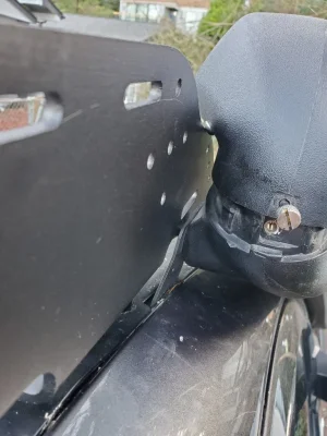
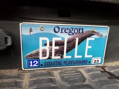
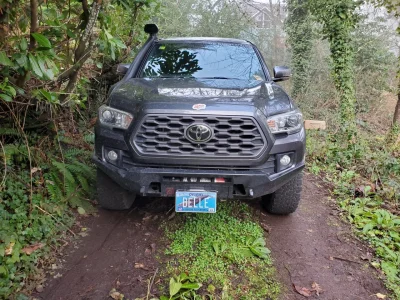
New plates are in!!! Now I just have to figure out how and where to mount the front (Oregon requires front plates) on my Proline bumper.
I'm thinking that I can fab a bracket to bolt on to the top of the bumper, and install it so that the plate is snug up to the grill, and out of the way of the sensors and front cam.
I'm thinking that I can fab a bracket to bolt on to the top of the bumper, and install it so that the plate is snug up to the grill, and out of the way of the sensors and front cam.
Attachments
Last edited:
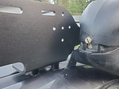
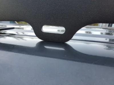
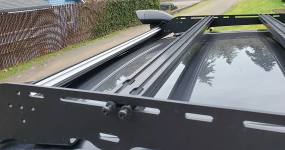
Well, after months of back and forth with Prinsu (CBI), I finally got the information that I had been missing to get the rack installed properly.
Basically, needed to remove the mounting bracket for the desert air intake, and then bolt the dai to the siderail, using the bolts that held it to the bracket.
When properly put together, it also fixes the low-hanging leg that was touching the roof.
So now I just need to devise a locking mechanism to keep my traction boards safely mounted up there, among other things, and get my light bar.... w00t!
Attachments
@fourgotten, This is what I did. Technically I have a front plate if I ever get stopped. I am sure you can probably fab something up better.New plates are in!!! Now I just have to figure out how and where to mount the front (Oregon requires front plates) on my Proline bumper.
I'm thinking that I can fab a bracket to bolt on to the top of the bumper, and install it so that the plate is snug up to the grill, and out of the way of the sensors and front cam.

That works, I suppose. 
I did wind up getting a front bracket. Not sure that I love it, and will probably modify it to make it more functional, but as long as it's within the law, right?
I did wind up getting a front bracket. Not sure that I love it, and will probably modify it to make it more functional, but as long as it's within the law, right?
Also, that bracket that I got doesn't exactly stay in the position that I set it, so my front plate tends to be at an angle similar to your, though a little less down.@fourgotten, This is what I did. Technically I have a front plate if I ever get stopped. I am sure you can probably fab something up better.
Well, I finally buckled down and finished the Up Down Air system install. I got things sussed out a but, a couple of weeks ago, and I have video of most of the process to put together and slap onto da YouseToobz to help other folks.
So the system that I got was supposed to fit a 3gen Tacoma. The tech with whom I spoke, Ashlyn, sent over some pics of her install and that helped a little but there were still some issues.
The mounting bracket for the regulator and hub of the system is supposed to use the bolt holes where a standard transmission would keep the clutch cylinder and share a bolt hole with that plastic bracket that comes up from the fuse box. One of those holes would line up.
Wound up machining the holes in the main part into slots so that it would span those two bolt hole.
However the L-shaped part that shares the bolt hole with that plastic bracket... well, it just waren't quite right. Wound up having to cut off about 1cm from the end and drilling a new hole. Covered the bare metal with touch-up paint to prevent corrosion and got that sucker installed a few weeks ago.
I also installed the front Shrader valves at that time, and ran the air line across the engine compartment and to the front valves. I installed the valves through the little tab that hangs from the top of the wheel well and holds the frontmost clip for that mud barrier.
In retrospect, that was not the best place for it. It is a little too flimsy, and it wants two hands to connect the whip to it.
The rear, however, was problematic. The long hoses were not long enough.
I ordered 32 feet of hose, and some more push-to-connect fittings.
Then I had an epiphany: I could run the line that goes across the engine bay only to the passenger front, and then use the splitter on the driver side and the line going to the rear driver could get a T-connector and feed both rear tires while the other line from the Y-connector would feed the driver front.
So, I got out Ye Olde Fish Rods, and fished the hose down along the driver-side frame.
I was torn on which of the crossmembers to use for bridging to the passenger side, but opted with the one that's mid-way along the frame, since I could get my hands up in there.
Installed the T and a right-angle on the passenger side and ran the lines back to the wheels.
There is a perfectly sized hole through the frame right above the wheel, and I figured to use that on each side. The passenger was NBD, and installed like a dream.
The driver was a PITA because the gas tank armor and the frame supports were all up in mah bidniss. Finally, with the help of a fishing stringer, some duct tape, and industrial-strength profanity, I got it in place and the nut tightened.
Now to test.
Hooked up the compressor to the Shrader valve input on the regulator and nothing. Turns out that I didn't get it connected solidly. Oops. A little more poking and prodding at the regulator and I got air into the system. Victory!!!
Or, not...nit.... hissing sounds were issuing from both front valves and the driver rear. The push-to-connect fittings need some harder pushing and more cleanly trimmed ends on the hose. Apparently it needs to be almost perfectly cut (so sharpen up those hose cutters!).
Had to pull the passenger front and driver rear (of course - the difficult one) out, adjust the hose, and reinstall.
All better.
However, my initial test showed that the quick-release assist rings on the whips were not going to allow the quick-release connector to connector ate.
Adjusted the ring positions to an acceptable distance and hooked everything up... groovy.
System is pretty air-tight now, and all wheels can connect to it for filling and emptying.
Now I just need to get out in the dunes and play with it more. Bwahaahaha!
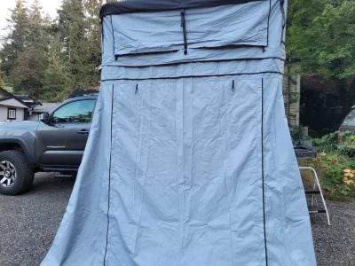
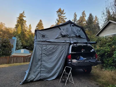
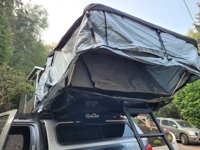
Well, some SoB pointed me at a deal that I couldn't refuse for a rooftop tent.
So, I drove an hour and some to pick it up, rather than pay $275 for it to be delivered.
The gent was very apologetic, as the Web site inventory didn't match in-stock inventory, so the color that I ordered was out.
They offered me a lighter greay and an awning to go with.... works for me!
So, now I have my own sleeping loft... the wife and dog won't climb the ladder to get in, so I guess that's all me, and they can sleep in the annex.
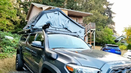
By a cool coincidence, the lighter grey matches my canopy (except the couple of scrapes I put in it, lifting that heavy beast into place) and the darker fly and window coverings match the truck!
Now I just need to suss the wiring to provide power up there.
So, I drove an hour and some to pick it up, rather than pay $275 for it to be delivered.
The gent was very apologetic, as the Web site inventory didn't match in-stock inventory, so the color that I ordered was out.
They offered me a lighter greay and an awning to go with.... works for me!
So, now I have my own sleeping loft... the wife and dog won't climb the ladder to get in, so I guess that's all me, and they can sleep in the annex.
By a cool coincidence, the lighter grey matches my canopy (except the couple of scrapes I put in it, lifting that heavy beast into place) and the darker fly and window coverings match the truck!
Now I just need to suss the wiring to provide power up there.
Attachments
Last edited:
It's me! I'm the SoB!! Yay tent!Well, some SoB pointed me at a deal that I couldn't refuse for a rooftop tent.
Haha. Congrats
-
About us
Tacoma3G.com is a forum for 3rd Generation Toyota Tacoma enthusiasts (2016-2024 model-years).
- Quick navigation
- User menu