This thread serves to document my buying experience and installation of my sliders that I ordered from Avid Off-road out in Queen Creek, AZ. These are 100% bolt-on, bolt to frame rock sliders. Customer service was excellent from day 1, and at no point did I ask a question and felt like I received an inadequate reply/answer.
*note: when I ordered my sliders, I had to contact Avid directly to place the order since their website wasn't completely updated, and this may still be true. Just fyi
They do not have installation instructions written up for their customers, and upon request Mr Brandon Harrop sent me an email with some photos that walked me through the process (which I will include in a document and attach to this thread), but I am the kind of person that prefers and appreciates more detail, even if it's something as simple as saying to just pick whatever holes that line up that you wish to use lol so, hopefully this write up will be something detailed that other customers can use for themselves.
At a glance, these are very well made. When I received them and got them home, I undertook the sweaty work of unwrapping them in the 100+ degree heat with the wife's kabar and discovered no marks or defects that would be obvious to me. Per an email with Mr Jon Pillon, the tubing material is 1-3/4 .120 wall HREW. I know some people prefer DOM, which is more pricey, so that's why I mentioned it.
These first photos are what you're looking at when you are underneath the truck, to the sides, and are basically observing what's there and kind of eyeballing your situation.
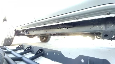
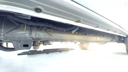
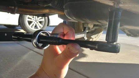
On each side of the frame, you can see 4 rivets arranged in a rectangular pattern. These will line up with 4 holes on the plates of your sliders. Also, on the base of the frame, pointing down towards the ground, there is a 14mm bolt (one on each side). This is unbolted and then secures the rear tab of the sliders to the frame. There is no hole available for the front tab, but that's no problem. Mr Harrop noted in his email that some people drill a hole to place a bolt there, but that it's unnecessary and that the sliders are strong without it. Below is a photo I took of me removing the driver side 14mm bolt. They were cemented in there pretty good, enough so that I had to grab a wrench and slip it over the handle of my socket wrench for additional leverage. Even so, I'll admit that I had to rush inside to poop after getting those two suckers out. So, be prepared for that possibility lol
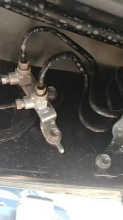
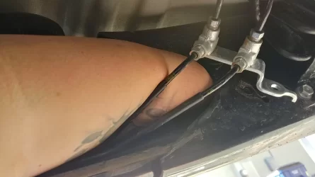
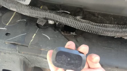
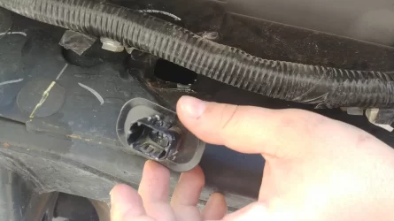
Next, I started removing the other stuff in the way. The below photos show the bracket for the brake lines, which I unbolted (12mm if I remember correctly), and the clips that are holding the lines. I unclipped the lines themselves to let me move stuff around more easily. I found that using a flathead screwdriver worked well for getting the clips to release the lines. Only broke one piece, so I'll take that as a win. There's also a plastic piece behind/under the brake line bracket, held on towards the top and inside of the frame by a 12mm (iirc) bolt, and then some sort of sticky tape or whatever at the base. Unbolt it and pull it out. There will be another one like this on the passenger side of the vehicle. I included a photo of me holding the piece that I am talking about, as well as a photo of it removed, and another photo of it intact on the passenger side of the truck.
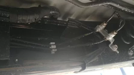
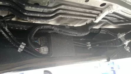
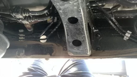
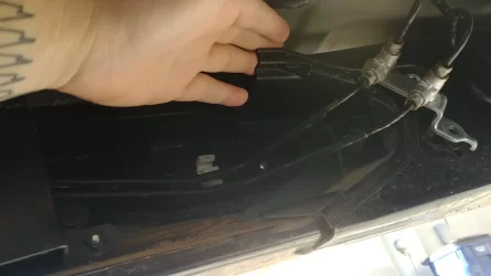
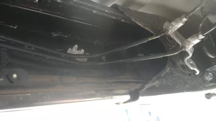
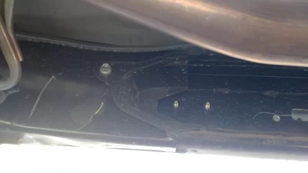
Next, I removed some more stuff. Who would've guessed that? lol You're going to need that 12mm again for these next 3: in the photo below, you'll remove that metal tab, as well as the two nuts that you see. For the nuts, for some reason my deep 12mm socket wouldn't grab them, but my shorty did. Doesn't really make sense to me, but if it works, then I won't complain. Keep that metal tab on the exterior of the sliders when you raise them up later to begin bolting them on.
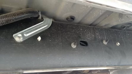
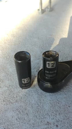
When you took off those 12mm nuts on the outside of the frame, you removed/loosened a black box on the inside of the frame. The brake lines run beneath it. There is a bolt for your sliders that will be placed behind that box but the bolt will need to go from the inside out because the box won’t go back on if not. That’s where you use the small plate that doesn’t have a nut welded to it (see included hardware from Avid). To further explain this, you have a bunch of metal plates with nuts welded onto them, and bolts that thread into them. Bolts on the exterior of the truck (outside - in) and the plates accept the bolts from the interior side of the frame. This space beneath the box that we're talking about is the exception for the reason above, and the bolt's plate does not have a nut welded on. It's got a big nut on it instead.
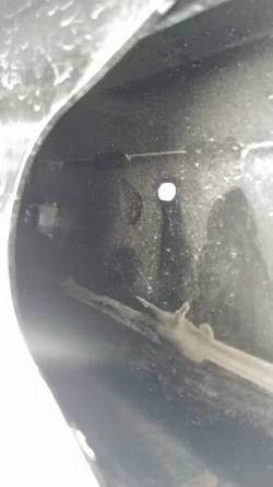
Now, you're going to need to reach your hand in the space you opened up by removing that plastic piece I showed a bit above. There's a rubbery tab thing, one for each side of the truck, that you'll be removing. It pops outward, toward the exterior of the truck/frame, and is just held on by some sort of glue or tape. I've included a photo of what I'm talking about as seen on the passenger side within the frame, but it'll be in the same spot on the driver side. Just a touch trickier to reach on the driver side because of the meat on my bones and the brake lines being right there.
We are now revisiting an earlier photo for the driver side wiring loom. The loom is held on to the exterior of the driver side frame by two tabs or clips, but these clips are anchored within that space that we've been hanging out in. Stick your hand in there with something that you think will effectively release those clips and have at it. The one closest to the entrance of that hole came out relatively easily for me, but I was cussing a fair bit by the time I got the second one that's further in there. I used a flathead screwdriver and eventually the loom was free. If it makes you feel better, I do think this was probably the extent of my frustration with this install overall. The loom remains outside when the sliders are bolted on, but there's space available where it clips back in, so ensuring it remains exteriorly isn't as much of a concern as it is with the metal tab that's next to it.

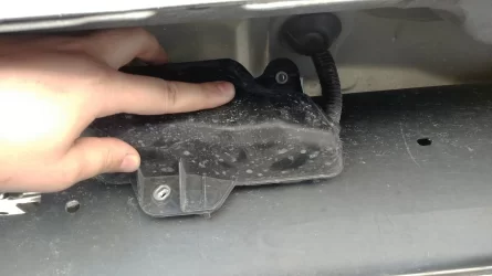
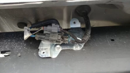
There's a box on the passenger side that has an electrical connection within it. Two 10mm bolts hold the plastic cover on (one towards the top and another on the bottom) and two 12mm hold the bracket to the frame. Remove all 4 bolts and remember to keep the electrical components and the bracket they're on to the outside of the slider plate as you mount your sliders. I forgot and couldn't figure out why the plate wouldn't sit flush with the frame. Had 4 bolts in and the sliders supported by them before I discovered my error. Don't be me, be attentive lol
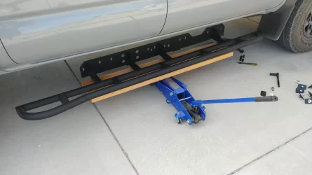
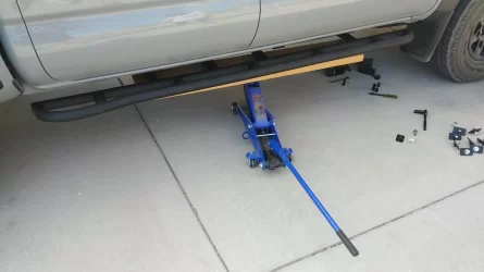
Now, I had my wife out there helping me out, but even so, lifting the sliders into place and bolting them in would have been a PITA. I had wooden boards lying around from back when I had a lowered car and needed the height they provided to get them on my Rhino ramps lol I placed one of these on the larger of my two hydraulic jacks (purely because it had a larger plate for lifting...more contact space would be more stable), and then placed the first slider on the board. Find the center of balance if you elect to go this route, otherwise it's just going to fall off, obviously. My driveway is on a slight incline and it still worked out fine. Take care when lifting so that it doesn't all come crashing down. Once you have contact with the frame of the truck, it'll be pretty stable.
Line up the holes and whatnot and start bolting them in. As I mentioned WAY up above, the 4 holes arranged in a rectangular pattern on the plate of the sliders match up with the 4 rivets on the outside of the frame, on each side. The place where you removed that terrible 14mm bolt on each side, the rear tab of each slider will go there, and the 14mm goes back in. You will need to place bolts and plates along the frame and plate of the sliders to bolt the sliders on. I placed one for each side within that space in the frame that was opened up, and then the others were placed according to specific directions (i.e. the one behind that driver side box that I discussed earlier) or they were placed based on what I could see from Mr Harrop's email and photos, OR based on where I thought they would fit best to properly support the sliders.
The bolts that thread into their plates are 17mm bolts. The exception is the one that goes behind that aforementioned box, from inside-out. I forget the sizing specifically for the nut and bolt individually, but either the nut or bolt is a 17mm and its corresponding piece of hardware is a 16mm.
Before we move on, I am sure that you can continue to safely and confidently follow this write up for bolt placement, because my sliders are clearly not going anywhere. They're sturdily held in place and my wife and I were even hopping on them without them budging at all. I weigh 215lbs, so I'm not a feather.
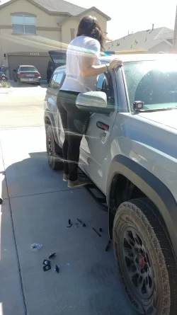
These next two photos below serve to demonstrate what I meant about the plates with the bolts threading into them, for anyone who may have had questions about that.
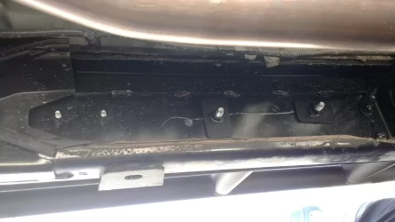
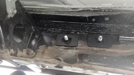
Moving on. I am now showing photos of bolt placement on the exterior side of the frame on the passenger side, moving from the rear of the truck to the front. Hopefully you guys can use these photos as a form of reference to where I placed my bolts, and where you can too.
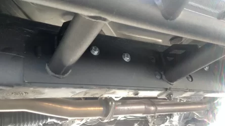
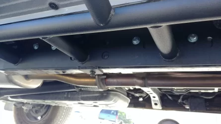
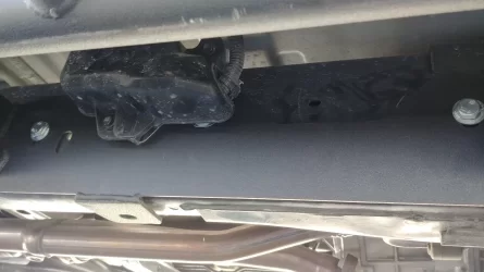
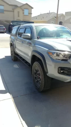
At this point, you're free to replace that plastic cover that was removed that covered the interior of the frame where you had to stick your arm in for the plate and bolt, and to bolt back on the bracket that held the electrical components as well as its plastic cover.
I have seen people occasionally ask others about how far their sliders stick out from the truck. I measured from the bit right below the doors, which is painted whatever color your truck is (so the base of the exterior of the body I suppose), and at the front they come out about 3.5-3.75 inches. At the rear with the kickout, they came out a bit over 6 inches. For anybody that cares, I hope this answers any questions you may have had.
The next set of images is to be viewed as if you're moving from the front of the driver side of the truck to the rear.
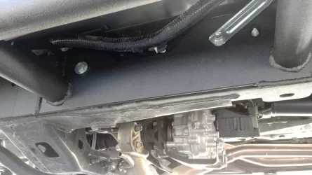
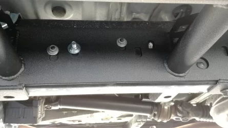
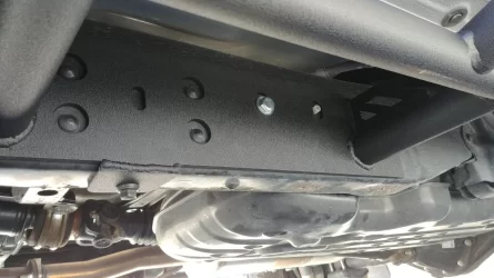
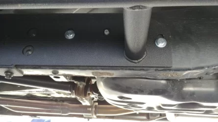
Start replacing everything once the slider is bolted up. You can see in the first photo just above that the metal tab next to the wiring loom (it actually holds the loom further up) has been reattached through the exterior of the slider plate and back into the frame and in the second photo, the nuts you removed earlier are back in place, meaning the black box over that one bolt and plate is back in its original place. The difference is that now, washers have been added beneath those nuts. They are included with the hardware that Avid sends, and they are there because otherwise the nuts would be too small compared to those holes to hold onto the slider plate I think. Replace the driver side plastic cover that sits beneath the brake line bracket, bolt that bracket back up, make sure your brake lines themselves are back at home in their clips, and clip the wiring loom that is exterior to the frame back into its spot. I was only able to use one of the clips since the other hole is now covered by the slider plate, but no worries, it's not going anywhere.
You may have noticed that on the passenger side, I have 5 plates/bolts in place, and only 4 on the driver side. I simply couldn't find another spot for the 5th, so maybe it's just an extra that Avid includes for you. Otherwise, I suppose it could have gone towards the very front of the slider plate on that driver side. There's an available hole in the plate, and behind it is a rubber piece within the frame. However, my arm simply couldn't reach that far within the frame so even if i cut out a hole for bolt and tried that, it wouldn't work anyhow.
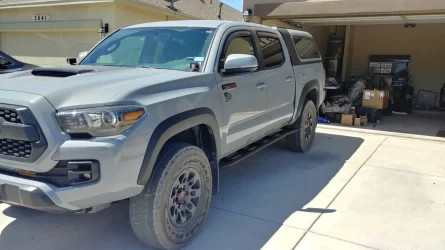
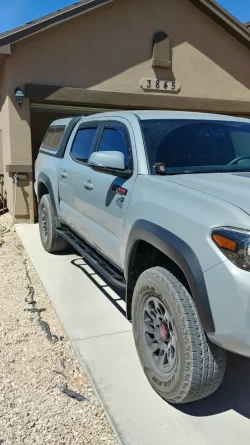
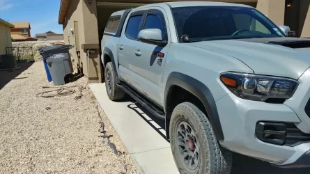
At any rate, I'm not worried. Like I mentioned up above, the sliders are clearly not going anywhere. Hopped up and down on them, on both sides, and all we accomplished was rocking the truck a bunch lol I'm very happy with the end result. They look great, they absolutely appear to be very well made and sturdy and I am sure that they will protect my truck very well if I hit anything with them.
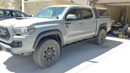
The list of attachments for this thread also includes a PDF of the email that Mr Brandon Harrop with Avid sent me, to help me along with the install.
Hopefully this write up has been appropriately detailed and helpful to anyone who reads/uses it. Feel free to ask me any questions that you may have.
*note: when I ordered my sliders, I had to contact Avid directly to place the order since their website wasn't completely updated, and this may still be true. Just fyi
They do not have installation instructions written up for their customers, and upon request Mr Brandon Harrop sent me an email with some photos that walked me through the process (which I will include in a document and attach to this thread), but I am the kind of person that prefers and appreciates more detail, even if it's something as simple as saying to just pick whatever holes that line up that you wish to use lol so, hopefully this write up will be something detailed that other customers can use for themselves.
At a glance, these are very well made. When I received them and got them home, I undertook the sweaty work of unwrapping them in the 100+ degree heat with the wife's kabar and discovered no marks or defects that would be obvious to me. Per an email with Mr Jon Pillon, the tubing material is 1-3/4 .120 wall HREW. I know some people prefer DOM, which is more pricey, so that's why I mentioned it.
These first photos are what you're looking at when you are underneath the truck, to the sides, and are basically observing what's there and kind of eyeballing your situation.


On each side of the frame, you can see 4 rivets arranged in a rectangular pattern. These will line up with 4 holes on the plates of your sliders. Also, on the base of the frame, pointing down towards the ground, there is a 14mm bolt (one on each side). This is unbolted and then secures the rear tab of the sliders to the frame. There is no hole available for the front tab, but that's no problem. Mr Harrop noted in his email that some people drill a hole to place a bolt there, but that it's unnecessary and that the sliders are strong without it. Below is a photo I took of me removing the driver side 14mm bolt. They were cemented in there pretty good, enough so that I had to grab a wrench and slip it over the handle of my socket wrench for additional leverage. Even so, I'll admit that I had to rush inside to poop after getting those two suckers out. So, be prepared for that possibility lol

Next, I started removing the other stuff in the way. The below photos show the bracket for the brake lines, which I unbolted (12mm if I remember correctly), and the clips that are holding the lines. I unclipped the lines themselves to let me move stuff around more easily. I found that using a flathead screwdriver worked well for getting the clips to release the lines. Only broke one piece, so I'll take that as a win. There's also a plastic piece behind/under the brake line bracket, held on towards the top and inside of the frame by a 12mm (iirc) bolt, and then some sort of sticky tape or whatever at the base. Unbolt it and pull it out. There will be another one like this on the passenger side of the vehicle. I included a photo of me holding the piece that I am talking about, as well as a photo of it removed, and another photo of it intact on the passenger side of the truck.


Next, I removed some more stuff. Who would've guessed that? lol You're going to need that 12mm again for these next 3: in the photo below, you'll remove that metal tab, as well as the two nuts that you see. For the nuts, for some reason my deep 12mm socket wouldn't grab them, but my shorty did. Doesn't really make sense to me, but if it works, then I won't complain. Keep that metal tab on the exterior of the sliders when you raise them up later to begin bolting them on.


When you took off those 12mm nuts on the outside of the frame, you removed/loosened a black box on the inside of the frame. The brake lines run beneath it. There is a bolt for your sliders that will be placed behind that box but the bolt will need to go from the inside out because the box won’t go back on if not. That’s where you use the small plate that doesn’t have a nut welded to it (see included hardware from Avid). To further explain this, you have a bunch of metal plates with nuts welded onto them, and bolts that thread into them. Bolts on the exterior of the truck (outside - in) and the plates accept the bolts from the interior side of the frame. This space beneath the box that we're talking about is the exception for the reason above, and the bolt's plate does not have a nut welded on. It's got a big nut on it instead.
Now, you're going to need to reach your hand in the space you opened up by removing that plastic piece I showed a bit above. There's a rubbery tab thing, one for each side of the truck, that you'll be removing. It pops outward, toward the exterior of the truck/frame, and is just held on by some sort of glue or tape. I've included a photo of what I'm talking about as seen on the passenger side within the frame, but it'll be in the same spot on the driver side. Just a touch trickier to reach on the driver side because of the meat on my bones and the brake lines being right there.


We are now revisiting an earlier photo for the driver side wiring loom. The loom is held on to the exterior of the driver side frame by two tabs or clips, but these clips are anchored within that space that we've been hanging out in. Stick your hand in there with something that you think will effectively release those clips and have at it. The one closest to the entrance of that hole came out relatively easily for me, but I was cussing a fair bit by the time I got the second one that's further in there. I used a flathead screwdriver and eventually the loom was free. If it makes you feel better, I do think this was probably the extent of my frustration with this install overall. The loom remains outside when the sliders are bolted on, but there's space available where it clips back in, so ensuring it remains exteriorly isn't as much of a concern as it is with the metal tab that's next to it.

There's a box on the passenger side that has an electrical connection within it. Two 10mm bolts hold the plastic cover on (one towards the top and another on the bottom) and two 12mm hold the bracket to the frame. Remove all 4 bolts and remember to keep the electrical components and the bracket they're on to the outside of the slider plate as you mount your sliders. I forgot and couldn't figure out why the plate wouldn't sit flush with the frame. Had 4 bolts in and the sliders supported by them before I discovered my error. Don't be me, be attentive lol


Now, I had my wife out there helping me out, but even so, lifting the sliders into place and bolting them in would have been a PITA. I had wooden boards lying around from back when I had a lowered car and needed the height they provided to get them on my Rhino ramps lol I placed one of these on the larger of my two hydraulic jacks (purely because it had a larger plate for lifting...more contact space would be more stable), and then placed the first slider on the board. Find the center of balance if you elect to go this route, otherwise it's just going to fall off, obviously. My driveway is on a slight incline and it still worked out fine. Take care when lifting so that it doesn't all come crashing down. Once you have contact with the frame of the truck, it'll be pretty stable.


Line up the holes and whatnot and start bolting them in. As I mentioned WAY up above, the 4 holes arranged in a rectangular pattern on the plate of the sliders match up with the 4 rivets on the outside of the frame, on each side. The place where you removed that terrible 14mm bolt on each side, the rear tab of each slider will go there, and the 14mm goes back in. You will need to place bolts and plates along the frame and plate of the sliders to bolt the sliders on. I placed one for each side within that space in the frame that was opened up, and then the others were placed according to specific directions (i.e. the one behind that driver side box that I discussed earlier) or they were placed based on what I could see from Mr Harrop's email and photos, OR based on where I thought they would fit best to properly support the sliders.
The bolts that thread into their plates are 17mm bolts. The exception is the one that goes behind that aforementioned box, from inside-out. I forget the sizing specifically for the nut and bolt individually, but either the nut or bolt is a 17mm and its corresponding piece of hardware is a 16mm.
Before we move on, I am sure that you can continue to safely and confidently follow this write up for bolt placement, because my sliders are clearly not going anywhere. They're sturdily held in place and my wife and I were even hopping on them without them budging at all. I weigh 215lbs, so I'm not a feather.

These next two photos below serve to demonstrate what I meant about the plates with the bolts threading into them, for anyone who may have had questions about that.


Moving on. I am now showing photos of bolt placement on the exterior side of the frame on the passenger side, moving from the rear of the truck to the front. Hopefully you guys can use these photos as a form of reference to where I placed my bolts, and where you can too.


At this point, you're free to replace that plastic cover that was removed that covered the interior of the frame where you had to stick your arm in for the plate and bolt, and to bolt back on the bracket that held the electrical components as well as its plastic cover.
I have seen people occasionally ask others about how far their sliders stick out from the truck. I measured from the bit right below the doors, which is painted whatever color your truck is (so the base of the exterior of the body I suppose), and at the front they come out about 3.5-3.75 inches. At the rear with the kickout, they came out a bit over 6 inches. For anybody that cares, I hope this answers any questions you may have had.
The next set of images is to be viewed as if you're moving from the front of the driver side of the truck to the rear.


Start replacing everything once the slider is bolted up. You can see in the first photo just above that the metal tab next to the wiring loom (it actually holds the loom further up) has been reattached through the exterior of the slider plate and back into the frame and in the second photo, the nuts you removed earlier are back in place, meaning the black box over that one bolt and plate is back in its original place. The difference is that now, washers have been added beneath those nuts. They are included with the hardware that Avid sends, and they are there because otherwise the nuts would be too small compared to those holes to hold onto the slider plate I think. Replace the driver side plastic cover that sits beneath the brake line bracket, bolt that bracket back up, make sure your brake lines themselves are back at home in their clips, and clip the wiring loom that is exterior to the frame back into its spot. I was only able to use one of the clips since the other hole is now covered by the slider plate, but no worries, it's not going anywhere.
You may have noticed that on the passenger side, I have 5 plates/bolts in place, and only 4 on the driver side. I simply couldn't find another spot for the 5th, so maybe it's just an extra that Avid includes for you. Otherwise, I suppose it could have gone towards the very front of the slider plate on that driver side. There's an available hole in the plate, and behind it is a rubber piece within the frame. However, my arm simply couldn't reach that far within the frame so even if i cut out a hole for bolt and tried that, it wouldn't work anyhow.
At any rate, I'm not worried. Like I mentioned up above, the sliders are clearly not going anywhere. Hopped up and down on them, on both sides, and all we accomplished was rocking the truck a bunch lol I'm very happy with the end result. They look great, they absolutely appear to be very well made and sturdy and I am sure that they will protect my truck very well if I hit anything with them.


The list of attachments for this thread also includes a PDF of the email that Mr Brandon Harrop with Avid sent me, to help me along with the install.
Hopefully this write up has been appropriately detailed and helpful to anyone who reads/uses it. Feel free to ask me any questions that you may have.
Attachments
Last edited:
