• Welcome to Tacoma3G.com, a free resource for 2016-2023 Toyota Tacoma owners!

    This website is the passion-project of a USMC veteran/mechanic, @Tyler. I created Tacoma3G.com to share my knowledge of this subject with others and to provide like-minded folks with a comfortable space to ask questions and create 'build threads' within our Tacoma Forums. Now, if the format of this website is confusing to navigate for you, or if you're interested in my full mission and T3G's history, check out the Help and About pages.

Lets Get Committed

Mr Hushwing

3️⃣ Silver
Tacoma3G Supporter
Joined
Mar 5, 2021
Messages
38
Reaction score
76
Age
41
Location
Grand Junction, CO
2017 TRD OR DCSB Auto
Magnetic Gray
Starting to finally find time where i can begin sharing my build. Be fore warned, its all built by me from scratch unless otherwise noted which at some point will be the case along the adventures.

To begin, lets get into the truck. Its a Magnetic Grey 2017 short bed 4x4 with the TRD Offroad package to include the crawl control but no real extras outside of that like adaptive cruise stuff.

Upgrades Before I got my hands on it=
-Repaired from Salvage (bought it with 12k miles for $25k all stock)


Upgrades after I got my hands on it=
-Pizza Cutter 235/85/16 Toyo AT3's

From the tire install, I quickly found myself above Ouray, CO on Poughkeepsie Gulch for my first adventure and shake down. Needless to say, I did not make "The Wall" without help from a winch. I was at about 18 psi looking back, plus it was just drying from a small rain storm, and my inexperience played the biggest part. If im being honest i was also scared of inflicting major damage. It was new to me...
IMG_7840.jpg
 
Then like many of us, this buck comes out of left field and decides to t-bone the truck at maybe 25mph, not a straight panel was left down the drivers side including the cab corner.
IMG_20200622_063352.jpg
IMG_20200622_063300.jpg
 
Now, im not the greatest weld fab guy. Lets make that clear up front. But I have a process, and i do not have deep pockets, nor do i care to finance anything at all costs. So, im left to my limited budget, wild imagination, a few grinders, a millermatic 212, time+energy and best of a goofy tiled garage floor thanks to the weird owners we bought our house from (that poor tile has no idea what its in for).

So, naturally it needs a bumper. Looking for something affordable, simple lines, a diy pre cut kit, 3/16 steel plate and it could certainly be designed for something else.

I found a diy pre cut kit thst you bend and weld up yourself meant for jeep Cherokee xj types I think. Comes with a winch box and ill adapt it to the truck. Whatever kills a deer at this point, but something i can customize and get great clearance with for approach angles. Like, stupid high.... Be warned.....i clearanced the grill for added height.

I started by fabbing out the bumper kit. I found it needed 9 inches added on each side of the winch box. Once i had the width, i set out to delete factory junk. Cutting bumper wings, grill and whatever. Photos are limited in this process as i was going like mad.
IMG_20200825_195130.jpg
IMG_20200825_195134.jpg
IMG_20200823_114306_01.jpg
IMG_20200823_192024_01.jpg
IMG_20200823_192036_01.jpg
IMG_20200823_194050_01.jpg

As you can see here, ive got it super tucked into the grill. I like the look but struggled with the wings of the bumper kit. Needless to say I brought it forward more before fully committing myself. But seriously, that approach angle i would later find to be awesome in what i can get away with on the trail on 31's!!!
IMG_20200829_183649_01.jpg
IMG_20200829_190720_01.jpg


IMG_20200829_191535_01.jpg
 
Shortly after getting it mounted, painted with Sherwin Williams DTM paint, i found i like to remove paint with a grinder and do more welding. It happens. I get excited, impatient and shit, next thing you know ive made a mistake.

Anyway, i thought it needed a square bar. So i made one. It was extremely rediculous and after getting made fun of by my daughters and wife..... I lowered it.
IMG_20200902_173550_01.jpg
Because its what we as spouses do..... Build dumb shit for people/family to laugh at, then make a course correction.
IMG_20200902_182211_01.jpg
 
So true, and it was my breaking point for better or worse to dive in and get committed to some serious tomfoolery..... Stay tuned... It gets worse
Whelp. At least she's already salvage :)

nice truck, looking forward to the build.
 
Oh man do jeeps have everything for these new owners to accessorize their rigs. And nearly all of it being bolt on. Toyota: get your poop in a group. Do not put off getting rock sliders as I did. Dont follow my example. I waited, thought i could get a piece of "The Wall" again without help. I did, but i brought home a piece of it with me in my passenger rocker. So lets get really committed on this one.

Anyways, onwards and upwards. Case in point: Boatside rock sliders. I love the clean look. Its nice and protective. Nothing hanging low to get snagged. Lets see how badly I can get myself in a pickle here. Im going for lightweight.... First and foremost. 16ga square tube in 2x2 and some 3/16 plate steel and for good measure in keeping the kiddos from snapping a leg a little 1" angle iron.

Began by getting some measurements. I really want a combo of boatside and your typical rock slider. I landed at cutting the plate steel with a plasma cutter i think if i remember right, first line was at 1", second at 4", third at 4" and the final at 1". All cuts i made sure to leave little tabs every so often to allow easier bending, hold a shape and it seemed to serve its purpose well doing so.
PXL_20210304_230933557_exported_5990_1615047229351.jpg
PXL_20210304_223826377.jpg


Hopefully by this picture, youll start to understand why its a committed thing... Im planning to partially mount these in the door jambs!!! Jesus this is escalating a lot. Its time to find some structural rivets....
IMG_20210304_154031_01.jpg
 
Once I had the two sides bent up to where i liked. I began the fitting process. That eventually lead me to discovering the flange which goes into the door jamb area cannot be 3/16 steel. But, it could be 1/16. So I tried ordering online just to see what that experience was like, I think if a project comes up again, i may try it out again. Downside is your limited to 4' lengths. Shitty deal, but shipping is dumb above that, so just buy local unless its something weird. Im sure 16 or maybe 14 ga sheet cut into some flatbar would do, but i didn't have to commit to a whole sheet online, which was perfect.

PXL_20210306_181058667.jpg


Next, i found thst i needed to break each one apart into two separate pieces to allow me to mount the lower half onto the pinch weld after locating its position forward and aft. Once there, i drilled my first hole on center and made that carry onto to the pinch weld. Simply from there, i installed a grade 8 bolt of the 3/8ths i think and tightened it down. It held itself in place at that point, allowing me to drill a hole every 8 inches roughly. It was nice to be this far and things working out step by step as I was really shooting from the hip. But once all the bolts were installed, i got the millermatic 212 out and ran a solid bead one each bolt head fixing each permanently to my rock sliders. Only way as i would not be able to reach any bolts with a wrench once everything was put together. The tape on the thumb was holding meat together... Buried my thin kirf blade into my thumb as i absentmindedly choked up on my grinder.
PXL_20210307_190458766.jpg

Heres a view underneath the truck.
PXL_20210307_201206543.jpg

Once i had both pieces in place for each i got committed with the welder, and moved on to fabricating up some crash bars for them.
PXL_20210307_201201089.jpg

Using 16 ga 2x2 box tubing i found where i personally preferred them to stick out as well as where i wanted the kickout located.
PXL_20210307_201220636.jpg

Yes i went and bought a properly guarded grinder designed for my favorite Diablo brand 6" thin kirf cut off wheels after the incident.
PXL_20210307_201758878.jpg
PXL_20210306_212258336.jpg

I know what your thinking, those could spear a critter. So i reversed those cuts later at front and rear.

Of course, in true green fashion here, i slopped some paint on. I kept the ends open as i felt better about reaching trapped dirt buildup at the carwash and im glad i did.
PXL_20210308_000625578.jpg
 

Attachments

  • PXL_20210307_184159077.MP.jpg
    PXL_20210307_184159077.MP.jpg
    440.3 KB · Views: 58
Darn these photos giving away my secrets. If i can pass along any wisdom from here on, is to really pay attention to details. You get the best weld fitments by using an ironing board as your weld fab table. Its just the facts.
 
I ended up getting the rock sliders finished in time for a trip to Moab. It was this trip where i found along the Hells Revenge trail, I made a great decision on my front bumper, but more importantly, my rock sliders saved me on the back end of Hells Revenge.

Luckily, i didnt damage anything really, but i found i had a knack for dragging my receiver hitch..... Pretty much every hard angle as well as my frame bottom on sharp brake overs.

Now my fabricating thoughts are wanting to jump ahead, but i know the first step to fixing things was getting the factory exhaust out and fab in a re routed system.

Heres a teaser......i need to break down photos out of videos from that build first, but i thought a photo would be nice.
PXL_20210401_210403954.MP.jpg
 
Wow man! Loving watching this. Everyday I want to cut and weld on my truck but don't have the guts. Thank you for this!
 
Wow man! Loving watching this. Everyday I want to cut and weld on my truck but don't have the guts. Thank you for this!
I know that feeling OzarkLander. These trucks are incredibly simple thankfully, despite modern circuit boards running everything. Hopefully i can inspire folks to get out there and fabricate more after watching my mistakes, or seeing my approach. I think for me out of all honesty, was the sheer cost of making a purchase for anything aftermarket bolt on....... It was basically a mortgage payment for each item. Rock sliders for instance, are every bit of $600 and north depending on brand and design. So for me and my pockets, im trying to save that for something i need and must purchase. However, there is something to be said and argued in favor of purchasing bolt on $1000 rock sliders. TIME. How much is your time worth? For me its more about keeping my skills growing and a sense of pride that its built, not bought. So, make a plan on graph paper, make a list of steps. Just get it broke down so you can make an informed decision on cutting, as im sure if youre considering it, youre most likely very capable. If it helps, this truck is my daily lol. I drive nearly 90 miles a day four days each week to work. I spend a lot of time doing 60+ mph on that 90 miles. This truck has to remain reliable, keep its mpg during the week, but capable on the trails over any given weekend. I have some crazy 😦 things in store for this build, so maybe something will inspire you to bust out that grinder and get committed lol..... Thanks again
 
Lets dive into the parts i got delivered for this exhaust project. Im doing this because as we all know, the factory crossover is really..... really ......dumb.

So, parts were ordered off of eBay and summit. Actually, Summit was used for the 3" stick of exhaust tube and the rest being the 2.5" tuning diy kit; v band clamps; and two 50' rolls of fiberglass exhaust wrap in black came from eBay.

Lastly, i decided to give Paradox muffler a try.
PXL_20210331_132326689_exported_273863.jpg
PXL_20210331_132326689_exported_423503.jpg

I feel confident that getting it somewhat close to equal lengths for tye down pipes and merging them behind my transfercase should be the ticket. Im still questioning my Paradox muffler choice however. Im not as young as I once was, and it may prove to be too much noise.
 
Pie cuts... Dont have any experience making them. So after some youtube i dove right in as my tight spacing had me feeling like it was the best way to go about running this exhaust system. Plus it would have to be routed out the side where i could kind of play around with them since it wouldn't be permanent. As a flatbed is certainly next on the list. I keep putting off skids for some reason. Mostly because im scared of getting the angles decent. Anyway, pie cuts, then build as I go like i always do with a general idea in my head to start with.

To start with you need a line to start from down the length of the pipe and another 180 degrees out from that. Some simple math will get you there to the second line. Diameter x Pi then divide that by 2 and you should know where to set that second line. Eyeball it sure, you could, but maybe this requires some detail.
PXL_20210331_135447535_exported_96061.jpg


PXL_20210331_144813609_exported_16966.jpg


I needed a two tight radius 90's. So just get all your pie cuts done, then clean the burrs off them all and finally weld them up.
PXL_20210331_154224172_exported_25066.jpg

Now i need to fab up that 2.5" exhaust T so i can bring the two sides together and jump up to 3" single to carry on back.
PXL_20210331_175931763_exported_289874.jpg

Cut the horseshoe in half and then i cut it down the middle of the elbows to leave me enough to make a 3" round id pipe to slip some short 3" over and weld it up.
PXL_20210331_183433351_exported_43079.jpg
PXL_20210331_183555514_exported_78700.jpg
at this point. Its time to commit and cut and unbolt to remove that old factory exhaust
PXL_20210331_184809229_exported_59666.jpg
out of the way. I of course saved a section of the down pipes where the O2's are, but deleted the second cats and never looked back.
PXL_20210401_141550808_exported_33629.jpg

Once i had the short section of downpipes cut off as im utilizing the bolt flange and O2's, i need to get them married up to the 2.5" tube.
PXL_20210401_143017862_exported_63045.jpg
PXL_20210401_143017862_exported_71641.jpg
 
Because i don't have access to a lift or exhaust jacks, I'm left to work from the floor like the rest of us. So you should he able to identify with the struggles. Everything is tack welded here. Once i like it, i tack it really well to prevent movent during removal for final weld up. I wanted to get the up pipes hung first and get a piece of angle iron clamped across the frame to support the two sides with some scrap steel tacked up for holding final location.
PXL_20210401_150416626_exported_599.jpg

PXL_20210401_151439862_exported_157333.jpg

Fixed up where i wanted them i moved on to located roughly where i wanted the 90 degree elbows to be for tying in the exhaust T. From there a simple mark and two cuts later, i had the two pipes shortened and ready to fit up the T.
PXL_20210401_150416626_exported_25429.jpg
PXL_20210401_150812589_exported_12166.jpg
PXL_20210401_160822459_exported_16000.jpg

PXL_20210401_150416626_exported_599.jpg
now the tight radius 90's to jog over the exhaust from on center of the driveline tothe passenger side where the original exhaust continued on back where ill try out the Paradox.
PXL_20210401_161632810_exported_49100.jpg
PXL_20210401_163203212_exported_32100.jpg
 
Once the exhaust was all tacked together and exhaust hangers were installed, i removed the system from the truck and fully welded everything. Since the newly routed exhaust is spending time next to brake lines, fuel lines and transfercase, it also got wrapped and I added a few heat shields for good measure.
PXL_20210401_170142176_exported_5500.jpg
PXL_20210401_170142176_exported_76833.jpg
PXL_20210401_180730195_exported_6933.jpg

In hindsight, 3" is a bit big for these v6 motors and deleting the second cats really changes the motors sound all while introducing header echo. All my design worked great though. Exhaust is out of the way for a skid plate build being the biggest!! Fuel lines and brake lines never get heated, and transfercase actuator does not warm up. I noticed just by the seat of my pants feel, that my powerband moved significantly towards the higher end of the rpm band. Not something i liked, especially for a motor already anemic in the torque department down low when offroad.

So ill stop here for now, as this gets changed after the next project build.
PXL_20210401_210403954.MP.jpg
 
In my ongoing efforts to gain clearance, while making my Tacoma more functional in simple ways like just carrying things to the house from Home Depot, it seemed a natural next step for me.....
PXL_20210407_145756649.jpg

A few measurements from the truck later and i drew up a flatbed in a width that wouldn't look farmtruckish...... Not sure if Ill get this the first time around, but lets get committed on this one.
 
A few hundred bucks later, i had fresh steel and began cutting based off my drawing. Since i both like my wheelbase and hate my 5 foot bed length, i decided the new flatbed would max out in length at 6 feet. This may prove to be great for utility, while suffering in the appearances department.

Step one- pre cut all the steel into a kit that is ready for weld up
PXL_20210408_200308012.jpg

Getting everything pre cut, makes for a fun weld up and thats assuming i get it correct. First i got the flatbed frame welded up as I know going into this, I am going to struggle with centering the darn thing on the truck.
PXL_20210409_182305621.jpg

After a good buddy came over, i was able to get the bed removed and begin problem solving.
PXL_20210410_175422281.jpg

As you can tell by the side exit exhaust, I had already begun struggling with how loud the exhaust is. Taking it from dumping under the truck to a side exit proved futile..... Darn thing has some kick to it. Ill address this during the flatbed build. Unfortunately for me, i end up making several exhaust changes, but for your amusement itll be a good laugh.
PXL_20210410_175429763.jpg
 

Attachments

  • PXL_20210408_200305860.jpg
    PXL_20210408_200305860.jpg
    994.3 KB · Views: 75
Centering proved difficult. At least for me. Just looking at the truck frame alone, as its design isn't a clear square, plus the rear axle is offset slightly to the right. I landed on using the rear of the cab to help get me started with a laser. The cab has those formed extrusions and the shortest being in the middle seemed an ideal starting point. Out of the six bed bolts, ill utilize four. So a crossbar at front and rear to capture the bolts and build off of proved to work well enough.
PXL_20210410_182505060.MP.jpg

PXL_20210410_183304062.jpg

The front bolted in where i was happy enough to move on to the rear where i knew id be figuring out just how much rake or height to be adding as the frame by design drops as it continues to the back. The original bed even accounts for this as well with added height underneath.
PXL_20210410_192213089.MP.jpg

I found an 1 1/4 did the trick knowing i could always add more if it seemed incorrect. Now on to the main runner tubing that runs forward and aft.
PXL_20210410_194546598.jpg

With main runner tacked in, i had imagined the flatbed deck height somewhere at or above the cab vents.
PXL_20210410_200942659.jpg

So i added some scrap to the flatbed frame to help me hold the frame on the tubes as im doing this on my own with no help. It ended helping a lot. Just a little loud when the frame crashed onto them after i slid it over into place. You can see the scrap tacked on in the photo. Roughly 3/4 of an inch down.
PXL_20210410_220410640.jpg

PXL_20210410_220207623.jpg

I liked my cab clearances, but was laughing out loud at myself as this bed height was crazy high and funny.... This looked good in my mind, but in reality was crazy tunes. Trust me, i verified with a few friends. Only one thought it was cool for the underbed storage possibilities.
 
With input from trusted folks I rely on, I played it safe and lowered it 5 inches.
Plus my wife, had weighed in and I tend to listen at times when she holds her ground on how rediculous some of my intentions are. Especially since she was being so wonderful in supporting me doing such a crazy change to the Tacoma in the first place.
PXL_20210411_161955413.jpg

PXL_20210411_162042340.jpg

Settled on the height, i dove straight in on welding in my supports that would hold the lightweight cedar plank (fencing from Home Depot) bed I have planned.
PXL_20210411_184448882.MP.jpg

PXL_20210411_192328625.jpg

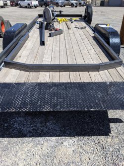
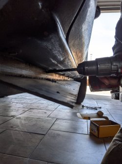
😆...... Next is my first rendition for the exhaust taking it from a side exit and being extremely obnoxious and hoping or trying to tame it a bit and run it out the back under the flatbed with another crazy idea that came to me.
 
Finally, i can re route the exhaust out the back and make my first attempt at getting the exhaust under control. Shooting here to introduce some back pressure in an effort to move the powerband back down lower and maybe quiet it a bit.

First i needed to bring it up from under the truck.
PXL_20210411_210908729.jpg
PXL_20210411_210927996.jpg

And now some dumb thinking on my part. The idea might have worked some if i had maybe found a way to re introduce the exhaust flow back into itself upstream a bit. In hind sight, it ended up being more a weld fab practice session and figuring out its getting time for a TIG machine.
PXL_20210411_211103971.jpg
PXL_20210411_213213399.jpg

PXL_20210412_005650262.jpg
PXL_20210412_005659909.jpg

Now i let myself marinate on that stupid decision and continued on to the tail light. Im a bit pumped to be honest about these tail lights.
 
I ordered these tail lights off of Amazon. They are bolt on and perform all functions in one light aside from reverse lights.
I was hoping to recess them in, but went a whole other direction as i began building the light bucket from some 16 ga 2x2 square tubing. I welded up caps on each end and then cut the rectangle box in half lengthwise to reveal two buckets which i welded to the back.
PXL_20210412_151451824.jpg

With both sides attached really well, i put a protective lid over the top which sticks out maybe a 1/4".
PXL_20210412_151522991.jpg

Here is the light in the running light mode, which everytime you turn on the lights it looks like a tracer worm working around the outside before fully lighting.
PXL_20210412_172536957_exported_13993.jpg

PXL_20210412_172536957_exported_16226.jpg

And here is the brake light which like a motorcycle, flashes really bright a few times before coming on.
PXL_20210412_172536957_exported_3232.jpg

Turn signals are like a mustangs tracer from inside moving out. I love these and a huge improvement over stock.
 
Once I had the two sides bent up to where i liked. I began the fitting process. That eventually lead me to discovering the flange which goes into the door jamb area cannot be 3/16 steel. But, it could be 1/16. So I tried ordering online just to see what that experience was like, I think if a project comes up again, i may try it out again. Downside is your limited to 4' lengths. Shitty deal, but shipping is dumb above that, so just buy local unless its something weird. Im sure 16 or maybe 14 ga sheet cut into some flatbar would do, but i didn't have to commit to a whole sheet online, which was perfect.

PXL_20210306_181058667.jpg


Next, i found thst i needed to break each one apart into two separate pieces to allow me to mount the lower half onto the pinch weld after locating its position forward and aft. Once there, i drilled my first hole on center and made that carry onto to the pinch weld. Simply from there, i installed a grade 8 bolt of the 3/8ths i think and tightened it down. It held itself in place at that point, allowing me to drill a hole every 8 inches roughly. It was nice to be this far and things working out step by step as I was really shooting from the hip. But once all the bolts were installed, i got the millermatic 212 out and ran a solid bead one each bolt head fixing each permanently to my rock sliders. Only way as i would not be able to reach any bolts with a wrench once everything was put together. The tape on the thumb was holding meat together... Buried my thin kirf blade into my thumb as i absentmindedly choked up on my grinder.
PXL_20210307_190458766.jpg

Heres a view underneath the truck.
PXL_20210307_201206543.jpg

Once i had both pieces in place for each i got committed with the welder, and moved on to fabricating up some crash bars for them.
PXL_20210307_201201089.jpg

Using 16 ga 2x2 box tubing i found where i personally preferred them to stick out as well as where i wanted the kickout located.
PXL_20210307_201220636.jpg

Yes i went and bought a properly guarded grinder designed for my favorite Diablo brand 6" thin kirf cut off wheels after the incident.
PXL_20210307_201758878.jpg
PXL_20210306_212258336.jpg

I know what your thinking, those could spear a critter. So i reversed those cuts later at front and rear.

Of course, in true green fashion here, i slopped some paint on. I kept the ends open as i felt better about reaching trapped dirt buildup at the carwash and im glad i did.
PXL_20210308_000625578.jpg
Rock Sliders look great, to bad you didnt have them on first.
 
Towing. Its important to me and keeping the factory setup was worth a try. More or less, i am after increased clearance for departure angle. I have lost count the number of times ive drug the thing across something, and at times loose momentum when crawling. So lets get committed here with a bit of delicate destruction.
Im using a plasma torch with a gouging tip as i just want to rid the factory receiver of its factory welds.
PXL_20210413_231435428_exported_3866.jpg
PXL_20210413_231435428_exported_15333.jpg

Not the best, but it worked great. Now a few love taps and ive got it all separated.
PXL_20210413_231435428_exported_38066.jpg

Now i can bolt it in, and get it flipped and welded.
 
Bolted each side up to the truck frame real loose like. Allowed enough slop to slip the upside down receiver back in. Once i tightened frame mounts up i welded it back in place where the factory had welded before. This was so nice of a change for departures and not dragging or leaving my mark all over Top of The World in Moab.
PXL_20210430_230227109.jpg

It’s funny that you posted this today. My dad and I were just talking about the money people spend on flat beds to get more clearance. Then you see that trailer hitch hanging all the way down in the factory spot. 🤦‍♂️
 
It’s funny that you posted this today. My dad and I were just talking about the money people spend on flat beds to get more clearance. Then you see that trailer hitch hanging all the way down in the factory spot. 🤦‍♂️
Right! I completely agree, and its nice to know im not the only one to think like this. Thanks for the comments and support. Im trying to currently decide on headache rack design and ideas on tie down anchor points using recessed stuff possibly.
 
Back
Top